Solenoid Door Lock Arduino

Relay Module Solenoid Door Lock How To Control Them With An Arduino Door Locks Arduino Programming Tutorial

Arduino Solenoid Door Lock Using Rfid In 2020 Arduino Rfid Arduino Arduino Circuit

Solenoid Door Lock Arduino In 2020 Arduino Arduino Robot Arduino Projects

Arduino Solenoid Door Lock Using Rfid In 2020 Arduino Arduino Projects Door Locks

Controlling A Lock With An Arduino And Bluetooth Le Make Arduino Arduino Projects Bluetooth

Arduino Solenoid Door Lock Using Rfid In 2020 Rfid Arduino Arduino Arduino Projects
12vdc solenoid door lock.
Solenoid door lock arduino.

Controlling A Lock With An Arduino And Bluetooth Le Make Arduino Arduino Projects Bluetooth Gadgets

Solenoid Door Lock Contol Rfid Arduino Arduino Arduino Contol Door Lock Rfid Solenoid In 2020 Rfid Arduino Arduino Projects Diy Arduino

Solenoid Door Lock In 2020 Door Locks Door Lock System Arduino

Open Electric Door Lock Using Rfid Reader Security Access With Arduino Youtube Rfid Arduino Arduino Projects Diy Arduino

Arduino Door Lock With Password Arduino Arduino Projects Door Locks

Arduino Solenoid Door Lock Using Rfid Youtube In 2020 Arduino Arduino Projects Door Locks

Arduino Controlled Lock Box With Solenoid And Rfid Lockbox Electronics Projects Arduino

Arduino Rfid Door Lock In Action Rfid Arduino Arduino Rfid

Learn How To Make An Rfid Door Lock Powered By An Arduino And Solenoid Engine Rfid Arduino Arduino Arduino Sensors

F I V O D On Instagram How To Make Fingerprint Door Lock At Home You Need Adafruit Fingerprint Sensor Fingerprint Door Lock Fingerprint Lock Door Locks

Automatic Garden Watering System By Arduino Lcd Buttons Eeprom Solenoid Valve Motor And Underground Sprinkler Garden Watering System Underground Sprinkler Arduino

Arduino Rfid Solenoid Lock Youtube In 2020 Rfid Arduino Rfid Arduino

Arduino Rfid Door Lock Access Control Project Arduino Door Locks Arduino Projects

Unlock A Door With An Arduino And Your Smartphone Bluetooth Lock Smartphone Arduino

Pin On Instructibles

Arduino Keypad Password Arduino Arduino Lcd Arduino Projects

Remote Controlled Door Lock Using A Fingerprint Sensor Adafruit Io Remote Control Door Lock Door Locks Lock Style

Arduino Door Lock Using 4 4 Keypad And Servo Motor Program And Video Http Www Letsarduino Com Electronics Projects Electronics Projects Diy Diy Electronics

Arduino Door Lock With Password Door Locks Arduino Electric Lock
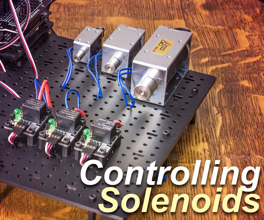
Control A Solenoid With Arduino Arduino Arduino Projects Radio Control Diy

Multi Task Arduino Uno Projets Arduino Arduino Electronique

Open Source Bluetooth Door Lock Make Diy Electronics Arduino Projects Smart Door Locks

Electric Lock Assembly Solenoid Cabinet Drawer Door Lock 12v Dc 1 1a Electronicslovers Official Store Electric Lock Electricity Drawers

Pin On Access Control Equipment Facility Maintenance And Safety
Source : pinterest.com
